Thursday, March 14, 2013

Wind Turbine Grid Connection

The wind turbines generate power by rotating a permanent magnet generator which generates three phase AC at the frequency of the turbine's rotation. The AC power from the generator is not only the wrong voltage to be connected to the local power grid, but also, as the wind speed changes so does the rotational speed of the turbine, and therefore the frequency of the power generated. The power from the generator therefore needs to be converted to DC and then fed into a special electronic device called an inverter, to ensure that it is always at the correct frequency and voltage for the local grid. 


Grid connection
Any power you generate will be first used by your own property, thereby saving you the maximum amount possible on your electricity bill. Any excess energy your wind turbine generates, e.g. on windy days or at night, is "spilled" to the power grid and your electricity supplier pays you for it. 

Grid connection
In order to charge your electricity supplier for any energy that you export to the grid, you need to have a new bi-directional electricity meter installed which will work both when you buy (import) and sell (export) electricity. Depending upon your local requirements, there may be additional meters needed to record energy generation to enable a claim for a Government subsidy. 
Shown below is a simplified block diagram of how all the system components are connected in the EU.
Companies however shortly hope to offer an off-grid package which when combined with a battery pack, and optionally solar PV panels and/or a diesel generator will enable the generation of “mains” power where there is no grid connection. For more information on small wind turbines go to small wind turbines.


Grid conection
The inverter also provides essential safety features to control the power output from the turbine, and to automatically switch off the current if the grid connection should fail. This means that should the grid connection fail, the inverters will switch off their output and there is therefore no danger to any maintenance engineers fixing the fault. This does however mean that the wind turbine will produce no power to the property if the mains connection fails. 

Tuesday, March 12, 2013

Lightning Protection of Wind Turbines


With the movement toward green energy, we all have to be thinking about new ways to do things, and wind turbine lighting protection is becoming a big concern. After all, any time you have a tall object sticking up high in the air and standing all by itself, lightning is going to strike it at some point. It is simply a matter of when. But there are some steps you can take to protect your wind turbine from lightning.

Surge protection is essential when it comes to wind turbine lightning protection. Here’s how it works:
· A lightning rod offers some protection to wind turbines, but it’s not enough. Rods only really protect against direct strikes, which are not going to be as common as other dangers from lightning. In order to have complete wind turbine lightning protection, you also need a lightning current arrester.
· Carbon brushes help to ground lightning off of wind turbines, creating an escape path for the lightning to get down to the ground. High quality brushes and brush holders will be able to stand up to the rigours of a lightning strike and protect your wind turbine.
· A class one arrester with spark gap technology is needed to comply with spark gap requirements in most cases. This arrester handles the largest majority of the strike’s power and keeps the class two arrester from overloading.
· A class two arrester connects to the class one arrester and handles all the initial conduction because it is able to respond rapidly to the threat posed by the lightning strike.

Protecting wind turbines from lightning strikes is a very new area of expertise, and it is definitely not one you want to overlook. Whether you’re a major power company with thousands of wind turbines or you’re a home-owner with one turbine in your backyard, you've got to protect your assets.
A lightning rod is a good place to start, but you can’t afford to miss out on the additional protection offered by a carbon brush and brush holder. Power surges won’t be a concern when you have this added insurance against damages.
Some companies offers wind turbine lightning protection. Their carbon brushes are specifically made to protect wind turbines from lightning strikes. They use low resistant grades of material to ensure that the lightning has a very easy path down to the ground that does not involve the overpowering of your wind turbine.

Grounding Brushes & Lightning Protection

Shaft Grounding Brush and Brush Holder
Companies offer several different carbon brushes for grounding applications. The most popular grounding brush is used as a shaft grounding assembly that diverts static and induced electric currents in motor shafts away from the bearings, protecting them from pitting and damage. Check out the Bearing Protector which is a brush and holder kit that can be easily installed on the end of the motor shaft.
Shaft grounding for use on Variable Frequency Drives (VFD) is the most popular use of the Bearing Protector. VFDs on both AC and DC motor induce harmful electrical current on the motor shaft that results in damage to the bearings.
Carbon brushes are also used to provide a path to ground for lightning on Wind Turbine applications. Low resistant grades of material are used to create a sure path to ground for lightning applications. The carbon brush and holder assembly is good insurance against lightning damage.

Lightning Protection for Wind Turbines

Wind Turbine Lightning ProtectionLightning strikes are a serious concern for wind turbines. Companies offer brush and brush holders that meet the rigorous demands of lightning protection. The brush grades perform well in high surges and are not prone to wear. Low resistivity ensures that electrical currents are directed away from crucial components. Brushes and brush holders are unsurpassed in quality and are a perfect safeguard for your investment.

Monday, March 11, 2013

Sizing Up Wind Energy and Transportation


One of the most popular trends in sustainable living is to go small: Live in a small house. Drive a small car. Have a small carbon footprint. So it seems contradictory that by going big—really big—energy equipment can become better for the environment.


But that's the case with wind turbines, according to a new study by the Swiss Federal Institute of Technology in Zurich.
Over the past 30 years, wind turbines have more than quadrupled in size. The blade diameter of today's models can surpass the length of a football field. In tandem with this growth spurt, land-based turbines in Europe became greener, the researchers concluded.
The report, published in the American Chemical Society's journal,Environmental Science & Technology, looked at the energy it took to build, transport, maintain, and dispose of turbines, as well as the electricity the turbines fed into Europe's power grid.
Turbines became more sustainable over time because larger models produce substantially more energy than smaller versions, the researchers said, but it does not take as much additional energy to manufacture bigger turbines. And as more turbines were built, manufacturers became more experienced and technology improved. With each doubling of wind-turbine manufacturing over time, the Swiss researchers found, the global warming potential per kilowatt-hour of electricity dropped 14 percent.
Marloes Caduff, the lead author, said she was surprised by how much the carbon footprint of the turbines declined over time. "I thought we would see a smaller effect," she said.
The industry, for its part, has tackled many of the challenges of larger turbines—for instance, how to move them from one place to another. Even so, companies believe there will be challenges for further growth in turbine size, even as the industry seeks to further improve their efficiency.

Why Bigger is Better
Bigger turbines reach higher above the earth's surface, where stronger winds blow. This allows them to extract more energy than their predecessors, and to work more efficiently.
In the 1980s, a typical wind turbine was rated with a capacity of about 50 kilowatts of electricity. Today, a large land-based turbine has a capacity of 3,000 kilowatts (3 megawatts). There are developers working on wind turbines as large as 10 MW for offshore installations. But on land, the most common turbines are from  1.5 MW to 2 MW. A 1-MW turbine can power 350 U.S. households for a year, according to Wind Energy America.
Using higher-capacity models reduces the number of turbines needed for a wind farm, says Fort Felker, director of the wind technology center at the U.S. Department of Energy's National Renewable Energy Laboratory in Golden, Colorado. For example, at today's capacities, 500 super-sized turbines could be installed instead of 1,000 smaller ones. By generating more energy with fewer machines, giant turbines can help reduce the price of wind power.

"The larger-size wind turbines result in dramatic reductions in the cost of [wind] energy," Felker said. "The cost has been reduced by a factor of ten or so, from unaffordable levels to where it is right now, able to compete with conventional power sources."

Sunday, March 10, 2013

Germany's Wind Energy Potential

Most of Germany’s pro-Energiewende voices think that Germany will far exceed its 2020 target of 35% clean energy. The Heinrich Böll Foundation, a Green think tank, is definitely among them. It argues that Germany could — with the right policies — go 100% renewable by 2050.
But for Germany to do it, argues the report "A European Union for Renewable Energy," there has to be greatly improved cooperation. The EU targets, road maps, and action plans are steps in the right direction, but they fall far short of a comprehensive EU common energy policy.

The report, commissioned by the Heinrich Böll Foundation European Union and prepared by independent experts, argues that most European countries' current energy grids are antiquated, nationally organized, and designed for fossil fuel and nuclear energy sources. The grids are composed mostly of one-way transmission cables connecting large production facilities, like coal-firing plants and nuclear reactors, to residential and commercial hubs.
Since the requisite storage technology is still largely undeveloped, what is needed are "smart," flexible, decentralized grids that crisscross the continent and beyond. In contrast to the "dumb" decentralized networks of the fossil-fuel age, a smart grid is a digital network that links customers with dispersed suppliers, like those operating wind parks and solar installations, through the Internet. The wider-reaching and "smarter" this network is, the better its ability to match weather-dependent supply surpluses and demand needs, both regionally and across borders.
Since grid construction needs as long as ten years to be realized, potential grid investors would need an unshakable commitment to renewable energies to invest in such a costly project. The report underscores a number of measures to get the ball on an all-European system rolling, including a "review" of the EU treaty that stipulates that the national states have full authority to determine their own energy supplies as they wish. Ultimately there must be a guarantee that nationally minded states don't obstruct plans for an European grid system.
As for Europe's current energy markets, they too tend to reflect national priorities and a fossil fuel-dominated system that the EU is supposedly committed to phasing out. The report argues that "open and hidden" subsidies for fossil fuels and nuclear must be abolished in order to even the playing field between renewable and conventional energies.
Moreover, Europe is a patchwork of diverse incentives, subsidies, and related taxes. About two-thirds of EU countries have a feed-in tariff along the lines of Germany's successful model. Its essence is that utilities are required to buy renewable energy from private producers at a higher-than-market price in order to cover the producer's investment in solar modules, wind turbines, biogas plants, or other production installations.


A key recommendation is the gradual harmonization of incentive and subsidy programs based on best practice models, including but not limited to the feed-in tariff. "To make prices within the internal energy market more transparent and attract cross-border investment," says Sascha Müller-Kraenner, the report's chief organizer, "today's systems have to be better connected, based on feed-in tariffs. Remuneration systems like tenders and auctions for big producers such as offshore wind farms can help make today's system even more competitive, but this doesn't mean replacing the most successful elements of the feed-in tariffs."

Saturday, March 9, 2013

Increasing the Efficiency of the Wind Turbine


Blades are important components that need to be matched with the wind speed environment in order to maximize the efficiency of a turbine. At low wind speed, more blades will be better and the blades should be long and wide. The blade pitch should be large. At high wind speed, the blades should be short and thin. The blade pitch should be small then. The number of blades is also an important parameter of a wind turbine. You may install 1 to 6 blades on the WindLab to see the effects, even if the blades are not balanced symmetrically.


However, it is difficult to test these parameters on a real wind turbine. Even if you can change the blade parameters on a real wind turbine, you cannot command the speed of the natural wind for you to test the result.
WindLab allows you to evaluate these parameters easily. It comes with a set of 3 blades and 1 vane, which are cut from flexible plastic (Polypropylene) sheets, for you to start with. The design concept is to let you design your own blades and vanes with easily available plastic or paper card sheets. Scissors and Punch are the standard stationery needed to work with your knowledge and imagination to create your own blades and vanes. You can modify the number, size and shape of the blades to see how the output is affected at different wind speed. You may also modify the size, shape and color of the vanes to make fun with it.
WindPitch allows the evaluation of Blade pitch and profiled blades. Mechanism for installing sheet blades is also included so that blade sizes and shapes can also be evaluated. However, WindPitch does not have an internal Gold Capacitor to store the generated electricity internally.


WindCharge can be used as a basic turbine for generating electricity for some applications. The blade pitch on the WindCharge Plus is optimized to an angle that maximizes the output of the turbine.

Friday, March 8, 2013

Blade Parameters


The blades should be designed so that the generator of the turbine rotates at the optimum speed at the desired range of wind speeds. The blades also affect the cut-in and cut-out wind speed of the turbines. The operation noise and vibration are also affected.
The parameters of the blades include shape, size, length, pitch, profile, material, weight, rigidity, number, etc.
Blades should be large in size, long in length, large in pitch and more in number at low wind speed.
The length of the blades can be modified to ones slightly larger for sites with low wind speeds or to ones slightly smaller for sites with high wind speeds.
Angle of Attack
Wind Turbine: Critical Angle of Attack with Respect to the Blade
The Critical Angle of Attack (αcritical) with Respect to the Blade
Tip Speed Ratio
Power Control Methods
Wind Turbine : Pitch Adjustment            Wind Turbine: Yaw Adjustment
Pitch Adjustment Yaw Adjustment

The amount of surface area available for the incoming wind is key to increasing aerodynamic forces on the rotor blades. The angle at which the blade is adjusted is referred to as the angle of attack, α. This angle is measured with respect to the incoming wind direction and the chord line of the blade. There is also a critical angle of attack, αcritical, where air no longer streams smoothly over the blade’s upper surface. Figure 2 shows the critical angle of attack with respect to the blade.
The tip speed ratio Î» (lambda) or TSR for wind turbines is the ratio between the rotational speed of the tip of a blade and the actual velocity of the wind.
Wind Turbine: Tip speed ratio =Tip speed of blade/Wind speed
This is an important parameter to evaluate the performance of a wind turbine. The tip speed of blade refers to the speed of rotation of the turbine. The higher the rotation speed of the turbine, the higher the output power of the turbine. Therefore if the TSR of a particular turbine is high, the efficiency will be higher.
The power output of the turbine can be optimized at the rated operating wind speed or limited at wind speed above the cut-out wind speed. The generator speed, blade angle adjustment, and rotation of the entire wind turbine can be controlled. Blade angle adjustment and turbine rotation are also known as pitch and yaw control, respectively. A visual representation of pitch and yaw adjustment is shown below: 
The purpose of pitch control is to maintain the optimum blade angle to achieve certain rotor speeds or power output. Stall and furl are two methods of pitch controls. By stalling a wind turbine, increasing the angle of attack, causes the flat side of the blade to face further into the wind. Furling decreases the angle of attack, causing the edge of the blade to face the oncoming wind. Pitch angle adjustment is the most effective way to limit output power by changing aerodynamic force on the blade at high wind speeds.
Yaw refers to the rotation of the entire wind turbine in the horizontal axis. Yaw control ensures that the turbine is constantly facing into the wind to maximize the effective rotor area and, as a result, power.  Because wind direction can vary quickly, the turbine may misalign with the oncoming wind and cause power output losses.

Thursday, March 7, 2013

How Much Power Can We Extract from the Wind


There is a limit to the amount of power we can extract from the wind.
Imagine a circular column of moving air, or wind, 2 meters across. We can calculate how much power is in that moving column of wind with the following


Wind Power = Air Density / 2 * Area * Velocity³

Where Air Density = 1.225 kgm³ at sea level, and Area = Pi * R², in our case, 3.14m²
Say we wanted to calculate the power at a wind speed of 5ms ( 18kmh, an average windy day ), we use
1.225 / 2 * 3.14 * 5³ = 240watts
How does wind speed affect the power? A great deal! If we double our wind speed to 10ms ( 36kmh ), we end up with 1920watts! That is why its important to know how much wind speed you have, and why windmills are put on tall towers, to get as many extra ms as possible.
Getting back to our average windy day wind speed, the 240 watts is how much power is in that column of moving air, but its not how much we can extract from it to do work.
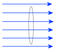
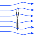
Air is a compressible fluid. If we face a 2 meter diameter disc into the wind, there will be some force against the disc from the wind, but not the full 240 watts worth. The wind will go around the disc, and most of the power goes with it.
What about a turbine? A turbine extracts much more energy from the column of moving air than the disc did, because the air is moving through the turbine, not around it. But some air will still go around. How much air goes around depends on many factors, like turbine design and loading.
There is a limit to how much energy we can extract from a column of moving air, called Betz.
And Betz tells us we can extract no more than 59% of the energy of the moving column of air. There is a point where the air will just go around instead of through, adding extra widgets to the turbine, funnels, etc, wont help, the air will just find it easier to go around. The maximum efficiency of a turbine can not exceed 59%.
In reality, the true power we can extract is much less than the Betz limit. A multi blade farm windmill has a typical efficiency of 15%, and modern large scale wind turbines are closer to 40% efficient.
So adding to our formula
Shaft Power = Air Density / 2 * Area * Velocity³ * Turbine Efficiency
where Turbine Efficiency would typically =15% to 40%
So if we attach a shaft to our 2 meter wind turbine, we would expect to extract about 96 watts of shaft power from the 5ms wind.
Next we use our shaft power to drive a alternator/generator, and again, we will get out less than we put in. A good alternator is somewhere between 70% to 90% efficient, so for the sake of this example, we'll use a 80% efficient alternator. 96 watts shaft power will convert to about 77 watts of electrical power.
So our 2 meter turbine, in a 5ms wind, could be expected to make 77 watts of electrical power. Adding to our formula again we get
Electrical Power = Air Density / 2 * Area * Velocity³ * Turbine Efficiency * Alternator Efficiency
where Alternator ( or Generator ) Efficiency would typically = 70% to 90%
Turbine diameter and wind speed have a dramatic effect on the electrical power we get extract. If we increase the turbines diameter to 3 meters, we get a turbine area of 7 meters, more than double the original turbines area. Punch the figures in and we get 535watts wind power, 214watts shaft power, and 171watts electrical power.
What about wind speed? Back to our original 2 meter turbine, double the wind speed to 10ms, gives us 1923watts wind power, 769watts shaft power, and 615 watts electrical power.
That's why its important to have the biggest turbine you can manage, and the best wind. A 1.5 meter turbine mounted on the roof or in the back yard is going to make very little power compared to a 3 meter turbine on a 10 meter mast, its all in the maths.

Tuesday, March 5, 2013

Offshore Wind Energy in U.S.A

The first offshore wind project was installed off the coast of Denmark in 1991. Since that time, commercial-scale offshore wind facilities have been operating in shallow waters around the world, mostly in Europe. With the U.S. Department of the Interior’s “Smart from the Start” initiative, wind power projects will soon be built offshore the United States. Newer turbine and foundation technologies are being developed so that wind power projects can be built in deeper waters further offshore.   
turnS

Wind energy has been utilized by humans for more than two thousand years. For example, windmills were often used by farmers and ranchers for pumping water or grinding grain. In modern times, wind energy is mainly used to generate electricity, primarily through the use of wind turbines. All wind turbines operate in the same basic manner. As the wind blows, it flows over the airfoil-shaped blades of wind turbines, causing the turbine blades to spin. The blades are connected to a drive shaft that turns an electric generator to produce electricity. The newest wind turbines are highly technologically advanced, and include a number of engineering and mechanical innovations to help maximize efficiency and increase the production of electricity. 
  
Offshore Wind Energy Resources
Offshore wind turbines are being used by a number of countries to harness the energy of strong, consistent winds that are found over the oceans. In the United States, 53% of the nation’s population lives in coastal areas, where energy costs and demands are high and land-based renewable energy resources are often limited. Abundant offshore wind resources have the potential to supply immense quantities of renewable energy to major U.S. coastal cities, such as New York City and Boston.  
Offshore winds tend to blow harder and more uniformly than on land. The potential energy produced from wind is directly proportional to the cube of the wind speed. As a result, increased wind speeds of only a few miles per hour can produce a significantly larger amount of electricity. For instance, a turbine at a site with an average wind speed of 16 mph would produce 50% more electricity than at a site with the same turbine and average wind speeds of 14 mph. This is one reason that developers are interested in pursuing offshore wind energy resources. The U.S. Department of Energy (DOE) provides a number of maps showing average wind speed data through its Resource Assessment & Characterization page and through National Renewable Energy Laboratory’s (NREL) MapSearch. 
Wind-Speed-MapS
 United States wind speeds at 80m hub height
(Credit: NREL)
Wind resource potential is typically given in gigawatts (GW), and1 GW of wind power will supply between 225,000 to 300,000 average U.S. homes with power annually.  In a July 2012 Technical Report, NREL estimates a gross wind power resource of 4,223 GW off the coast of the United States. That is roughly four times the generating capacity of the current U.S. electric grid. Even if only a fraction of that potential is developed, clearly there is enough offshore wind resource to power a substantial portion of our nation’s energy needs.
Wind speeds off the Atlantic Coast and in the Gulf of Mexico are lower than wind speeds off the Pacific Coast. However, the presence of shallower waters in the Atlantic makes development more attractive and economical for now. Hawaii has the highest estimated potential, accounting for roughly 17% of the entire estimated U.S. offshore wind resource. For additional information on NREL’s assessment of offshore wind power resource, see the publicationAssessment of Offshore Wind Energy Resources for the United States. Maps of renewable energy potential for multiple technologies, or state-by-state analyses, can be downloaded here
  
 Offshore-Wind-ResourceS
United States offshore wind resource by region and depth
(Credit: NREL)

Transport of Wind-Generated Energy
 ESPs
An Electric Service Platform (ESP) for an offshore wind facility.

All of the power generated by the wind turbines needs to be transmitted to shore and connected to the power grid. Each turbine is connected to an electric service platform (ESP) by a power cable. The ESP is typically located somewhere within the turbine array, and it serves as a common electrical collection point for all the wind turbines and as a substation. In addition, ESP’s can be outfitted to function as a central service facility, and may include a helicopter landing pad, communications station, crew quarters, and emergency backup equipment. After collecting the power from the wind turbines, high voltage cables running from the ESP transmit the power to an onshore substation, where the power is integrated into the grid.  The cables used for these projects are typically buried beneath the seabed, where they are safe from damage caused by anchors or fishing gear and to reduce their exposure to the marine environment. These types of cables are expensive, and are a major capital cost to the developer. The amount of cable      used depends on many factors, including how far offshore the project is located, the spacing between turbines, the presence of obstacles that require cables to be routed in certain directions, and other considerations.
Offshore Wind Energy Technology
The engineering and design of offshore wind facilities depends on site-specific conditions, particularly water depth, geology of the seabed, and wave loading. In shallow areas, monopiles are the preferable foundation type. A steel pile is driven into the seabed, supporting the tower and nacelle.  The nacelle is a shell that encloses the gearbox, generator, and blade hub (generally a three-bladed rotor connected through the drive train to the generator) and the remaining electronic components. Once the turbine is operational, wind sensors connected to a yaw drive system turn the nacelle to face into the wind, thereby maximizing the amount of electricity produced.
For more information about wind turbine technology, see NREL’s “Wind Energy Basics: How Wind Turbines Work.
Today’s offshore turbines have technical modifications and substantial system upgrades for adaptation to the marine environment. These modifications include strengthening the tower to cope with loading forces from waves or ice flows, pressurizing nacelles to keep corrosive sea spray from critical electrical components, and adding brightly colored access platforms for navigation safety and maintenance access. Offshore turbines are typically equipped with extensive corrosion protection, internal climate control systems, high-grade exterior paint, and built-in service cranes. To minimize the expense of everyday servicing, offshore turbines may have automatic greasing systems to lubricate bearings and blades as well as heating and cooling systems to maintain gear oil temperature within a specified range. Lightning protection systems help minimize the risk of damage from lightning strikes that occur frequently in some offshore locations. There are also navigation and aviation warning lights, regulated by the U.S. Coast Guard and the FAA. Turbines and towers are typically painted light grey or off-white to help them blend into the sky, reducing visual impacts from the shore. The lower section of the support towers may be painted bright colors to increase navigational safety for passing vessels. 
 RePower-5MWs
The Repower 5M turbine, offshore Scotland, one of the world’s largest wind turbines.
(5-MW, 126m tall, 45m depth)


To take advantage of the steadier winds, offshore turbines are also bigger than onshore turbines and have an increased generation capacity. Offshore turbines generally have nameplate capacities between 2 MW and 5 MW, with tower heights greater than 200 feet and rotor diameters of 250 to 430 feet. The maximum height of the structure, at the very tips of the blades, can easily approach 500 feet, and turbines even larger than 5 MW are being designed and tested for future use. 
While the tower, turbine, and blades of offshore turbines are generally similar to onshore turbines, the substructure and foundation systems differ considerably. The most common substructure type is the monopile—a large steel tube with a diameter of up to 20 feet. Monopiles are typically used in water depths ranging from 15 to 100 feet. The piles are driven into the seabed at depths of 80 to 100 feet below the mud line, ensuring the structure is stable. A transition piece protrudes above the waterline, which provides a level flange to fasten the tower. In even shallower environments with firm seabed substrates, gravity-based systems can be used, which avoids the need to use a large pile-driving hammer. Tripods and jackets foundations have been deployed in areas where the water depth starts to exceed the practical limit for monopiles.


Sunday, March 3, 2013

Stall Regulated Wind Turbines

Following on from the airfoil aerodynamics post, here is an overview of the important aerodynamic concepts for stall-controlled wind turbines. Stall control was the first really practical control system for large wind turbines, and was a logical development of the disc-area-regulation concept used on small wind turbines that regulated the power through varying the frontal disc area (typically pitching or yawing the rotor out of the wind after rated speed). A typical stall-control turbine is shown here, which is an NM52-900 that it is taken a picture of in Spain a few years ago (Pena Amada in Gallicia). It has a 52m rotor diameter, with the blades directly mounted to the hub with a fixed pitch(Stall).


The concept of stall control is that the power is regulated through stalling the blades after rated speed is achieved. As the rotational speed of the rotor is effectively constant, the AoA of the blades increase with increasing wind speed. As the wind speed increases the blades begin to stall, the lift drops, and the drag increases to a more inefficient L/D relationship at a higher AoA and thereby reducing the driving torque. There is little control of the blade aerodynamics, which means that the blade is typically designed such that stall occurs at rated wind speed with the most optimal AoA setting (the L/D sweet spot) occurring much earlier (around average wind speed if you are lucky!). You can really see this in the following figure of power curve.

As the blade pitch is fixed, the turbine rotor is quite simple as there is no blade pitch system required (no additional hydraulics, electrics, or pitch bearings!) making the turbine cheap and simple - these are very important characteristics for a turbine in my opinion, as the cost per kW.hr should really be the market driver.
Some of the drawbacks I think with this type are:
  • Turbines have reduced efficiency (Cp) towards rated speeds due to the higher AoA (reduced L/D)
  • Higher thrust coefficient (Ct) due to high AoA means:
  • Higher loads, particularly on blades and tower
  • Larger wake deficits resulting in greater array losses for the farm
  • Increased wake turbulence
  • Noisier due to higher AoA during operation
  • Can induce severe vibrations due to transition period around rated speed where blades are coming in and out of stall during each rotation
  • Sensitive to the blade's initial pitch setting (must be correctly set to account for local density)
  • Sensitive to dirty blades (rated power can be significantly reduced)
A derivative of this control system is the active-stall system, where the blades have a small amount of pitch control to allow power regulation after rated power is achieved; effectively the control system utilises the negative lift-curve slope characteristic of the airfoil in the post-stall condition, increasing the stall will reduce the power. This is a very popular system, and was first introduced on the NEG-Micon 54-950 and has been further optimised for use on the popular NM82-1650. Here's a picture of some NM82-1650 turbines checked in Australia (Wattle point, if you are really interested!).


Lastly if you wonder the comparison between stall regulated wind turbines and pitch controlled wind turbines see post  Pitch versus Stall

Saturday, March 2, 2013

Importance of the Location for Small Wind Turbines


Wind is the fuel that drives a wind turbine. A windmill needs to be placed where the wind is; putting it on too short a tower is like installing solar photo voltaic panels in the shade. Neither will work very well. Not just any wind will do, a wind turbine needs air that moves uniformly in the same direction. Eddies and swirls, ‘turbulence’ in short, do not make good fuel for a wind turbine. The rotor cannot extract energy from turbulent wind, and the constantly changing wind direction due to turbulence causes excessive wear and premature failure of your turbine. This means that you want to place your turbine high enough to catch strong winds, and above turbulent air. Since the tower price goes up quickly with height there is a limit to what is practical and affordable. This section is intended to help you decide what tower height works best.

The quick-and-dirty rule of thumb for turbine height is a minimum of 10 meters (30 feet) plus the length of a turbine blade above the tallest obstacle (trees, house etc.) in a 150 meter (500 feet) radius, with a tower height of at least 19 meters (60 feet). If the obstacle is more solid than a few trees (for example a whole tree line) then even more distance than 500' is needed, as will be described below.
This should really be regarded as an absolute minimum for a wind turbine; at 10 meters above an obstacle there will still be some amount of turbulence and additional clearance is highly desirable. Keep changes in height of obstacles in mind as well. For example, if you have trees that are expected to grow up to 60 feet high, it is advisable to use a 100 feet tower. Likewise, a 60 feet tower should only be used when the terrain is very, very flat with no obstacles in a wide area around, for example at the edge of the sea, or on top of a cliff with a clear area around it, or in the tundra. For most situations a 60 feet tower will only save a little money up front, while short selling energy production in the long run.

To go beyond the rule of thumb, the airflow over any blunt obstruction, including a tree, tends to create a “bubble” of turbulent air of twice the height of the obstacle, extending 20 times the height of the obstacle behind it. So, your 30 feet high house disturbs the air up to 600 feet away. That tree line with 100 feet trees disturbs the air up to 200 feet high at a distance of 1000 feet away! The figure above illustrates this. Locate your wind turbine either upwind of the obstructions, or far enough downwind. Notice from the figure that preference should be given to a site upwind of obstructions, but keep in mind that tall features downwind of the turbine can also influence the wind going through the blades, as shown in the figure.
Upwind and downwind are relative to the prevailing wind direction; where the wind blows from most of the time. A wind atlas can sometimes tell you what your prevailing wind direction is, and if there is one at all. Some sites have winds that did not read the rule book, and there it is equally likely to blow from more than one direction.
When it comes to wind turbines, the bottom of a hill, valley, or ravine makes for a poor place to site a windmill. The wind tends to drop in speed at the bottom of a smooth hill, then speed up as it goes up the hill, reaching around twice the wind speed at the top of the hill. The figure below shows this. You can use this effect to your advantage if you have hills on your property.

For obstructions that are not smooth, such as a cliff (i.e. a sudden rise in the landscape) it gets trickier: Sharp edges create turbulence, as illustrated in the figure below. The airflow at the top of the cliff can be stronger than the average wind speed in the area, but close to the cliff’s edge it may also be very turbulent, making it a poor site for a turbine. If you have a cliff edge on your property and want to use it for siting your turbine, you should still use a 60 feet high tower to get above turbulent air. Even if it seems that the wind is always blowing hard at the cliff’s edge.
The lee side (downwind of the prevailing winds) of a bluff object makes for a very poor wind turbine site. The bluff object will create large turbulence on its downwind side, and the average wind speed will drop off precipitously as well. This leaves no energy for the wind turbine to harvest.

There actually is a cheap way to visually find out at what height turbulent air ends, and smooth, laminar airflow begins. Just fly a kite at your proposed wind turbine location on a windy day, preferably when the wind is coming from the prevailing direction. To visualize airflow, use tape-streamers tied to the kite’s string every 15 feet or so (home improvement stores sell plastic marking tape in fluorescent colors for very little money). Wildly fluttering tape indicates turbulence, smoothly extended tape means smooth air. Be sure to take the angle of the kite’s string into account when calculating height.
The energy in the wind increases with the cube of the wind speed (P ~ v3), and wind speed increases with height. An increase of just 26% in wind speed means twice as much power available in the wind, and your wind turbine will produce almost twice as much. Double the wind speed and you an harvest almost eight times as much power! A small additional investment in tower height may therefore be well worth it, thanks to the increased energy production. If you know the annual average wind speed for your location (from weather data, a wind atlas, local weather station etc.) Weather data usually reports wind speeds at 10 meters above ground level, the spreadsheet can take care of translating that to a wind speed at turbine height. For a quick idea of how changes in tower height affect the power in the wind for an unobstructed site see the figure below.

The Danish Wind Power Association made a very nice, interactive, calculator that allows one to plug in various obstacles (for example, a row of trees), set their height and distance to the wind turbine, and visually show what effect this will have on wind speed and energy. The calculator shows the percentage of the wind speed at various distances and heights behind the obstacle. Keep in mind though that the effect of obstacles is not just to diminish wind speeds, but they also make the air swirl, creating turbulence. Turbulence is an energy thief when it comes to wind turbines.
If you have sufficient space for guy wires, we advise to use a tilt-up tower for your wind turbine. They are economical, costing only a little bit more than the cheapest type of tower (a fixed guyed tower), and allow the turbine to be installed on the ground. Maintenance can also be done on the ground, by tilting the tower down. This saves in crane expenses, and makes installation and maintenance much safer because the work does not have to be done at dangerous heights.
Another aspect of proper windmill siting is the distance from occupied buildings. All wind turbines produce some amount of sound. Even though the Scirocco is one of the most quiet wind turbines on the market (no, this is not just marketing hype, it really is quiet), it too produces sound. Some people find its sound soothing, since it tells them they are making energy, while it drives others absolutely bonkers. For that reason it is a good idea to place your wind turbine some distance away from your house, 100 feet is a good number for minimum separation. That is not to say that closer cannot be done, but you will have to honestly assess how the turbine’s sound will affect you. Generally, a Scirocco that is placed in smooth air will be almost inaudible unless the wind starts blowing hard. At that point the blades pitch to stall angle, causing the air to swirl across the blades instead of flowing smoothly, and this increases the audible sound. When this happens it can be heard over the wind when you are in close proximity (and downwind sound will carry further than upwind). There also is such a thing as too much distance, since the length and gauge of the wiring that is needed will increase. With the ever-increasing price of copper this makes it more expensive to install your turbine.
Since we are talking about buildings: Despite the current marketing pitch of many small wind turbine manufacturers and sales people, it is generally a very bad idea to mount a wind turbine (any turbine, not just a Scirocco) directly onto a building. The airflow that close to the building is generally very turbulent, leading to premature failure and poor power production. It is usually noisy too. Every wind turbine has some amount of vibration associated with it, and this too will be transmitted inside the house. We know, the thought of bolting a little turbine to the house, just over the roof line, to offset your electricity use (as that salesman put it) is appealing. The harsh reality is that it does not work: Several studies were done, involving dozens of roof-top-turbines. They all concluded that those turbines do not work. Their energy production is negligible, and some were even net-users of electricity (because their inverters draw power, even when nothing is going into the grid)!  Just say "no" to building mounted turbines!