Showing posts with label Wind Turbine Blades. Show all posts

Thursday, May 23, 2013

Siemens 75 m Wind Turbine Blade( World's longest )

Day by day wind industry is going to be massive. The next incredible new is from Siemens. They're building  the world's largest turbine with each blade 75 meters in length. Each blade is made by carbon fiber(Siemens believes the B75 blade is the world’s largest fiberglass component to be moulded in one piece.), and it will be working at coast of Britain in 2014. 

Siemens 6 MW offshore blade

The contract agreed on July 19, 2012 to supply 300 wind turbines with a capacity of 1.8 GW which will be installed between 2014-2017. The 6MW offshore prototype will be working for testing during the next year. 
This 6 MW offshore wind turbine has 154 meters diameter with a swept area of more than 18.600 square meters which is equivalent to the area of approximately two-and-a-half football fields. 6 MW offshore wind turbine can supply approximately 6000 European household with electricity. 

Siemens 6 MW nacelle

The blades will be built in factory in Aalborg, Denmark. One more important point is transporting for these giant wind blades. Normally the distance between factory and Britain is 330 km. But because of re-routing due to over size blades (bridges, roads... are considered) 575 km will be gone. 

Siemens blade transportation

Michael Suess, a board member for Siemens energy sector, said: 'Offshore wind energy has huge potential. Offshore wind conditions are strong and stable, enabling an energy yield which can be about 40 percent higher than onshore.'The United Kingdom, Denmark and Germany in particular are counting on the future of offshore wind energy. We are pleased that our long-term customer DONG Energy has chosen the latest generation of our wind turbines.'Together we are working to further reduce the levelised costs for this environmentally-friendly form of power generation.'

SWT 6.0 MW

Just to compare Airbus A 380 with Siemens 6 MW offshore wind blade !! 

Airbus A 380

Lastly, Vestas has also 8 MW offshore wind turbine with 164 meters diameter !! See: http://easywindenergy.blogspot.de/2013/05/vestas-v164-80-mw-offshore.html

Tuesday, April 30, 2013

Ice Effects on Wind Turbines

Wind turbines should be able to work really in hard conditions. Sometimes they must withstand  so cold weathers, sometimes so high temperatures which depends on where the turbine locates.  

Wind turbine blade with ice
Especially the blades are effected in an important manner from the cold weather. And sometimes the ices can be problem for wind turbines. That's why during development state, up to climate conditions of desired area which turbine will be located, some extra calculations must be done. One of this extra calculations is ice loads which is defined in guidelines. 

Ice loads
If the turbine continue to produce power in cold weather, ice can be seen on the blade. Due to ice, mass of the blade is changing which makes extra high loads on the some parts of the turbines. What's more if the ice is effecting the pitch motors, the turbine must be shut down by control mechanism. If not due to high rotational speeds, some parts of turbine can be damaged. 

Wind turbine blade with ice
To let the turbine produce power in worse weather conditions wind turbine ice protection system (WTIPS) is invented. It is deicing the blade's leading edge by pulsing power to safely shed ice. WTIPS is a electro-thermal device system using technology originally developed through a NASA Small Business Innovative Research. It is light weight, easy to install, digitally controllable with Plc systems and reliable.

Ice effects on wind turbine blades
To get an idea about ice effects on wind turbines you can watch the following video. The turbine continue working with icy blades. 


Saturday, April 27, 2013

Wind Turbine Blade Tests

Blade tests
If we look up to the wind turbine costs. It can be clearly seen that the blades have a huge importance for a wind turbine. Blades are used for capturing energy from the wind. Longer blades mean higher captured power. But when the blade length is increased, beside higher power, higher loads will also occur. After certain wind speed blades won't be able to withstand with higher loads and they will be broken which is not desirable situation. That's why the blade length is optimized.

Blade bending test
When the rotor is rotating, the blades have a certain rotational speed which is calculated before construction. After certain rotational speed, the turbine must be shut down to prevent collapsing. If not, the blades will turn faster and faster in high wind conditions. And due to high force at the tip of blade, it will tend to bend to the tower. As a result it will hit to tower.


Blade bending test
Bending property of the blade is so important and blade frequencies must be also calculated to prevent a resonance effect before construction. Due to all this stuff, some type of tests are made by blade manufacturers. Because they want to be pretty sure that their blades can withstand with all conditions in an efficient way. That's why as a first step, they are investigating the loads and they are making some experiments with blades which are showed in previous pictures.


Blade bending
As it seen in the previous photo, the tips of the blades bend to the tower due to wind. As in development stage, during investigating the loads, tip to tower distance in all extreme conditions must also be considered as it defined in guidelines.  

Friday, April 26, 2013

Why do wind turbines always have three blades?

If you have seen a wind farm, you have noticed that wind turbines have 3 blades. Why not 1 blade, 2 blades, 4 blades or 5 blades ? Because the aim is when the power is produced not to capture more wind. The aim is capturing wind with greatest efficiency. And as a result it is found that 3 blades is the most efficient and less troublesome way.
 Wind turbine with one blade
It is not common but when you see a wind turbine with one blade, you shouldn't surprise. It looks like a little different from the other common wind turbines even the working principle is same. Due to one blade, it is cheaper from the others. On the other hand the aesthetic of the one bladed turbine is a little worse. Whole wind energy sector compromise about 3 blade wind turbines due to aesthetic. If we look more detail, the efficiency of the one bladed turbine is higher, but the loads are also higher due to unbalance rotor. What's more it tends to spin faster. That's why it is much more noisy.

2 bladed offshore wind turbine
As it seen the previous figure, sometimes two bladed wind turbines can also be seen. The same phenomena about aesthetic is valid for two bladed wind turbine also. But this has higher efficiency than the one bladed and 3 bladed wind turbines. When we compare with 3 bladed wind turbines, the only advantage  is one blade is less, that's why it is cheaper. It is cheaper from the rotor side but on the other hand  because of higher loads the maintenance costs and the life of turbine must be considered also. 


3 bladed wind turbine 
Due to aesthetic, efficient loads 3 bladed wind turbines are much more common. When it is compared with the other types of wind turbines, powerful enough and it is less noisy because of tending to spin slower. Noise issue is also must be considered when a wind turbine constructed. Because of these reasons 3 bladed wind turbines are accepted in wind energy sector.


Wind turbine with 5 blade
When the number of the blades are increasing, normally cost of turbine is also increasing. That's why the turbines which have more than 3 blades seen rarely. If we look from the technical side, when we have more than 3 blades, we must make them lighter. When they are lighter, they will tend to spin faster and they will be broken. That's why generally it is not good idea to use more than 3 blades. 

Sunday, April 7, 2013

Wind Turbine Maintenance and Noise Issue

Wind Turbine Noise

Your neighbours' concerns relating to wind turbine noise are important. No matter the size of the wind turbine, the potential for turbine noise to bother other people always exists. Even if a wind turbine does not emit enough sound to violate any noise regulations, the noise it produces may still be objectionable to other people. Before building a wind turbine, familiarize yourself with the types of noise your wind turbine could make:
Aerodynamic noises may be made by the flow of air over and past the blades of the turbine. Such noises tend to increase with the speed of the rotor. For blade noise, lower blade tip speed results in lower noise levels. Of particular concern is the interaction of wind turbine blades with atmospheric turbulence, which results in a characteristic "whooshing" sound.
Mechanical noises may also be produced by components of a wind turbine. Normal wear and tear, poor component designs or lack of preventative maintenance may all be factors affecting the amount of mechanical noise produced.
Wind turbine noise 

How Loud Might a Wind Turbine Be?

At a distance of 250 m, a typical wind turbine produces a sound pressure level of about 45 dB(A) (decibels). As following figure shows, this sound level is below the background noise level produced in a home or office. Most small wind turbines, in fact, make less noise than a residential air conditioner.

Small Wind Turbines

The blades rotate at an average range of 175-500 revolutions per minute with some as high as 1150 rpm. Large turbines turbine blades rotate in the range of at 50-15 rpm at constant speed, although an increasing number of machines operate at a variable speed.
Comparison chart of decibel levels  from  a hypothetical wind turbine - noise level between that of the house and of the bedroom.
 Comparison of decibel levels from a hypothetical wind turbine (from 250 m away) with other sources of noise.

Maintenance

A wind turbine requires periodic maintenance such as oiling and greasing, and regular safety inspections. Check bolts and electrical connections annually; tighten if necessary. Once a year check wind turbines for corrosion and the guy wires supporting the tower for proper tension.
If the turbine blades are wood, paint to protect from the elements. Apply a durable leading edge tape to protect the blades from abrasion due to dust and insects in the air. If the paint cracks or the leading edge tape tears away, the exposed wood will quickly erode. Moisture penetrating into the wood causes the rotor to become unbalanced, stressing the wind generator. Inspect wooden blades annually, and do any repairs immediately.
After 10 years, blades and bearings may need to be completely replaced. With proper installation and maintenance, your turbine can last 20-30 years or longer. Proper maintenance will also minimize the amount of mechanical noise produced by your wind turbine.
Maintenance

Safety Concerns

All wind turbines have a maximum wind speed, called the survival speed, at which they will not operate above. When winds over this maximum occur, they have an internal brake and lock to prevent them from going faster than this survival speed.
For turbines operating in cold winter conditions, be prepared to de-ice as required, and store batteries in an insulated place.
Mounting turbines on rooftops is generally not recommended unless a wind turbine is very small (1 kW of rated output or less). Wind turbines tend to vibrate and transmit the vibration to the structure on which they are mounted. As a result, turbines mounted on a rooftop could lead to both noise and structural problems with the building and rooftop.
Safety Concerns

Monday, March 11, 2013

Sizing Up Wind Energy and Transportation


One of the most popular trends in sustainable living is to go small: Live in a small house. Drive a small car. Have a small carbon footprint. So it seems contradictory that by going big—really big—energy equipment can become better for the environment.


But that's the case with wind turbines, according to a new study by the Swiss Federal Institute of Technology in Zurich.
Over the past 30 years, wind turbines have more than quadrupled in size. The blade diameter of today's models can surpass the length of a football field. In tandem with this growth spurt, land-based turbines in Europe became greener, the researchers concluded.
The report, published in the American Chemical Society's journal,Environmental Science & Technology, looked at the energy it took to build, transport, maintain, and dispose of turbines, as well as the electricity the turbines fed into Europe's power grid.
Turbines became more sustainable over time because larger models produce substantially more energy than smaller versions, the researchers said, but it does not take as much additional energy to manufacture bigger turbines. And as more turbines were built, manufacturers became more experienced and technology improved. With each doubling of wind-turbine manufacturing over time, the Swiss researchers found, the global warming potential per kilowatt-hour of electricity dropped 14 percent.
Marloes Caduff, the lead author, said she was surprised by how much the carbon footprint of the turbines declined over time. "I thought we would see a smaller effect," she said.
The industry, for its part, has tackled many of the challenges of larger turbines—for instance, how to move them from one place to another. Even so, companies believe there will be challenges for further growth in turbine size, even as the industry seeks to further improve their efficiency.

Why Bigger is Better
Bigger turbines reach higher above the earth's surface, where stronger winds blow. This allows them to extract more energy than their predecessors, and to work more efficiently.
In the 1980s, a typical wind turbine was rated with a capacity of about 50 kilowatts of electricity. Today, a large land-based turbine has a capacity of 3,000 kilowatts (3 megawatts). There are developers working on wind turbines as large as 10 MW for offshore installations. But on land, the most common turbines are from  1.5 MW to 2 MW. A 1-MW turbine can power 350 U.S. households for a year, according to Wind Energy America.
Using higher-capacity models reduces the number of turbines needed for a wind farm, says Fort Felker, director of the wind technology center at the U.S. Department of Energy's National Renewable Energy Laboratory in Golden, Colorado. For example, at today's capacities, 500 super-sized turbines could be installed instead of 1,000 smaller ones. By generating more energy with fewer machines, giant turbines can help reduce the price of wind power.

"The larger-size wind turbines result in dramatic reductions in the cost of [wind] energy," Felker said. "The cost has been reduced by a factor of ten or so, from unaffordable levels to where it is right now, able to compete with conventional power sources."

Friday, March 8, 2013

Blade Parameters


The blades should be designed so that the generator of the turbine rotates at the optimum speed at the desired range of wind speeds. The blades also affect the cut-in and cut-out wind speed of the turbines. The operation noise and vibration are also affected.
The parameters of the blades include shape, size, length, pitch, profile, material, weight, rigidity, number, etc.
Blades should be large in size, long in length, large in pitch and more in number at low wind speed.
The length of the blades can be modified to ones slightly larger for sites with low wind speeds or to ones slightly smaller for sites with high wind speeds.
Angle of Attack
Wind Turbine: Critical Angle of Attack with Respect to the Blade
The Critical Angle of Attack (αcritical) with Respect to the Blade
Tip Speed Ratio
Power Control Methods
Wind Turbine : Pitch Adjustment            Wind Turbine: Yaw Adjustment
Pitch Adjustment Yaw Adjustment

The amount of surface area available for the incoming wind is key to increasing aerodynamic forces on the rotor blades. The angle at which the blade is adjusted is referred to as the angle of attack, α. This angle is measured with respect to the incoming wind direction and the chord line of the blade. There is also a critical angle of attack, αcritical, where air no longer streams smoothly over the blade’s upper surface. Figure 2 shows the critical angle of attack with respect to the blade.
The tip speed ratio Î» (lambda) or TSR for wind turbines is the ratio between the rotational speed of the tip of a blade and the actual velocity of the wind.
Wind Turbine: Tip speed ratio =Tip speed of blade/Wind speed
This is an important parameter to evaluate the performance of a wind turbine. The tip speed of blade refers to the speed of rotation of the turbine. The higher the rotation speed of the turbine, the higher the output power of the turbine. Therefore if the TSR of a particular turbine is high, the efficiency will be higher.
The power output of the turbine can be optimized at the rated operating wind speed or limited at wind speed above the cut-out wind speed. The generator speed, blade angle adjustment, and rotation of the entire wind turbine can be controlled. Blade angle adjustment and turbine rotation are also known as pitch and yaw control, respectively. A visual representation of pitch and yaw adjustment is shown below: 
The purpose of pitch control is to maintain the optimum blade angle to achieve certain rotor speeds or power output. Stall and furl are two methods of pitch controls. By stalling a wind turbine, increasing the angle of attack, causes the flat side of the blade to face further into the wind. Furling decreases the angle of attack, causing the edge of the blade to face the oncoming wind. Pitch angle adjustment is the most effective way to limit output power by changing aerodynamic force on the blade at high wind speeds.
Yaw refers to the rotation of the entire wind turbine in the horizontal axis. Yaw control ensures that the turbine is constantly facing into the wind to maximize the effective rotor area and, as a result, power.  Because wind direction can vary quickly, the turbine may misalign with the oncoming wind and cause power output losses.

Sunday, March 3, 2013

Stall Regulated Wind Turbines

Following on from the airfoil aerodynamics post, here is an overview of the important aerodynamic concepts for stall-controlled wind turbines. Stall control was the first really practical control system for large wind turbines, and was a logical development of the disc-area-regulation concept used on small wind turbines that regulated the power through varying the frontal disc area (typically pitching or yawing the rotor out of the wind after rated speed). A typical stall-control turbine is shown here, which is an NM52-900 that it is taken a picture of in Spain a few years ago (Pena Amada in Gallicia). It has a 52m rotor diameter, with the blades directly mounted to the hub with a fixed pitch(Stall).


The concept of stall control is that the power is regulated through stalling the blades after rated speed is achieved. As the rotational speed of the rotor is effectively constant, the AoA of the blades increase with increasing wind speed. As the wind speed increases the blades begin to stall, the lift drops, and the drag increases to a more inefficient L/D relationship at a higher AoA and thereby reducing the driving torque. There is little control of the blade aerodynamics, which means that the blade is typically designed such that stall occurs at rated wind speed with the most optimal AoA setting (the L/D sweet spot) occurring much earlier (around average wind speed if you are lucky!). You can really see this in the following figure of power curve.

As the blade pitch is fixed, the turbine rotor is quite simple as there is no blade pitch system required (no additional hydraulics, electrics, or pitch bearings!) making the turbine cheap and simple - these are very important characteristics for a turbine in my opinion, as the cost per kW.hr should really be the market driver.
Some of the drawbacks I think with this type are:
  • Turbines have reduced efficiency (Cp) towards rated speeds due to the higher AoA (reduced L/D)
  • Higher thrust coefficient (Ct) due to high AoA means:
  • Higher loads, particularly on blades and tower
  • Larger wake deficits resulting in greater array losses for the farm
  • Increased wake turbulence
  • Noisier due to higher AoA during operation
  • Can induce severe vibrations due to transition period around rated speed where blades are coming in and out of stall during each rotation
  • Sensitive to the blade's initial pitch setting (must be correctly set to account for local density)
  • Sensitive to dirty blades (rated power can be significantly reduced)
A derivative of this control system is the active-stall system, where the blades have a small amount of pitch control to allow power regulation after rated power is achieved; effectively the control system utilises the negative lift-curve slope characteristic of the airfoil in the post-stall condition, increasing the stall will reduce the power. This is a very popular system, and was first introduced on the NEG-Micon 54-950 and has been further optimised for use on the popular NM82-1650. Here's a picture of some NM82-1650 turbines checked in Australia (Wattle point, if you are really interested!).


Lastly if you wonder the comparison between stall regulated wind turbines and pitch controlled wind turbines see post  Pitch versus Stall

Sunday, February 24, 2013

Individual Pitching Control

How can we develop wind turbines that reduce the overall cost of electrical power generation? When answering this question, investment costs as well as operating and maintenance.

(O&M) costs have to be taken into consideration. One of the focal areas of this paper is load reduction as it can play a key role in increasing turbine efficiency and lifetime. When trying to reduce loads on turbine structures, designers focus on pitch control systems. We present recent technological developments and research results in this field, especially concerning Individual Pitch Control (IPC).


Given the opportunities and challenges in wind energy, we see the need for close cooperation between turbine designers and key system suppliers. This means companies combining their strengths and expertise by jointly engaging in research, as well as the development of prototypes and systems. Our partnership approach for developing future wind energy solutions is further explained at the end of this White Paper. Figure 1

Developments in the Wind Energy Sector
How are we going to meet our energy demands in the future? When governments and businesses worldwide draft strategies to answer this question, renewable energies play an increasingly important role. Among renewable energies, wind energy has gotten a head start in the race towards competitiveness. Electrical energy generated by wind power can already compete with energy generated by fossil or nuclear sources. [1]

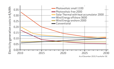
According to a study of the Fraunhofer ISE from December 2010, wind energy plants in locations with favorable wind conditions can already compete with conventional power plants. The costs for electricity generated by onshore wind parks are currently 0.06 to 0.08 €/kWh, which is in the range of electricity generation costs of conventional power plants using coal, lignite or nuclear fuels. [1] Consequently, wind parks are emerging from the state of research or pilot projects to commercially attractive investments. Large energy companies are increasingly investing in wind power. Among these investors are companies specialized in wind power but also electrical power suppliers who are relying on a mix of fossil, nuclear and renewable energy sources. When planning new wind parks, especially in Europe, one of the main hurdles is getting approval from authorities. Due to regulations with respect to landscape protection and noise control, the sites available for new wind parks are increasingly located offshore or, in the case of onshore installations, in remote areas. These sites are often characterized by poor access, extreme climatic conditions or non-ideal wind conditions. For the manufacturers of wind turbines this means facing new challenges: their wind turbines need to withstand extreme temperatures and work efficiently for a wider range of wind speeds. The installation of turbines in areas with poor access also places increased emphasis on operating and maintenance (O&M) costs. Figure 2

The growing importance of wind energy as a source for electrical power generation leads to stricter requirements concerning reliability and predictability of the power supply.  Meeting grid code requirements with respect to frequency and voltage becomes more and more important for operators of wind parks. Large energy companies engaged in the wind power business are likely to focus their development efforts on meeting these requirements. [2]

The necessity to lower the overall cost of electrical power generated by wind turbines (cost per mega watt) has led to a trend towards larger turbine sizes. Especially for offshore installations the cost of the foundation represents a substantial part of the overall investment cost. It proved to be more cost efficient to build wind parks with fewer large size turbines than a large number of smaller turbines. [3]

Evolution of Standard Rotor Diameters
However, larger turbines with longer rotor blades and higher tower structures are creating technical challenges for turbine designers. The longer the rotor blades, the stronger the effect of any in homogeneities of the incoming wind field. Examples of such in homogeneities are lower wind speeds close to the ground and higher speeds with increasing distance from the ground (wind shear). Such a gradient of the wind speed translates into an asymmetric load on the rotor blades. The feasibility and technical challenges of large wind turbines has been the subject of recent studies and publications, notably the upwind project sponsored by the European Commission. While the power output of commercial wind turbines is usually in the range of 1 to 7 MW, the upwind project evaluates the feasibility of a 20 MW turbine. [4] [5] 


Individual Pitch Control
How can designers build wind turbines with longer lifetimes? Recent economic and technical developments such as the pressure to reduce the overall cost of electricity generated by wind turbines, the necessity to reduce O&M costs as well as increased emphasis on reliability and predictability of power production make it urgent to find a technical solution to that question. Load reduction is a key element of the solution. In addition, load reduction gains an increasing importance due to the trend towards larger wind turbines. Individual pitch control (IPC) plays a key role in compensating loads. So what is IPC? Any pitch control system allows control of the turbine speed and consequently the power output. It also acts as a brake, stopping the rotor by turning the blades. Moreover, pitch control, especially an IPC system, has a role in reducing fatigue loads on the turbine structures. Recently developed wind turbines are variable speed turbines capable of adapting to various wind conditions. This adaption is realized via new generator concepts on the one hand, and a pitch control system on the other hand. Pitch control means the turning of rotor blades between 0° and 90°. When wind speeds are below rated power, typically below 12 m/s, the rotor blades are turned fully towards the wind which means that the pitch is positioned at 0°. Figure 4


At increasing wind speeds the pitch of the blades is controlled in order to limit the power output of the turbine to its nominal value. When wind speeds reach a predefined threshold, typically 28 m/s, the turbine stops power production by turning the blades to a 90° position.

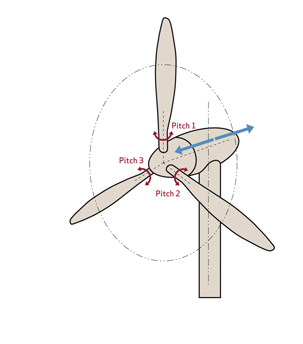
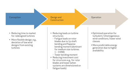
Collective pitch control adjusts the pitch of all rotor blades to the same angle at the same time. In contrast, IPC dynamically and individually adjusts the pitch of each rotor blade. Based on current individual loads this pitch adjustment is carried out in real-time. The main benefit of IPC is the reduction of fatigue loads on the rotor blades, the hub, and mainframe and tower structures. In order to compensate these loads, especially symmetric loads caused by inhomogeneous wind fields, the pitch of each rotor blade has to be adjusted independently from the other blades. A reduction of fatigue loads has two considerable advantages: It allows lighter designs and translates into longer lifetimes of wind turbines. What is meant by lighter designs? In cases where components are designed according to fatigue loads, a reduction of these loads allows savings in cost and material notably for the rotor blades and the tower structure, which are the most expensive elements of a wind turbine. Moreover, lighter rotor blades enable a more efficient turbine, especially in low wind conditions. Finally the load reduction through IPC gives designers the option to develop low wind turbines from existing designs, which means a reduction of time to market.

Load Reduction – A Technical Overview
During start-up, regular operation (power generation) and shutdown a wind turbine is subject to various forces causing peak loads and fatigue loads. In the context of this paper we shall focus on fatigue loads because they can be influenced by pitch control systems most effectively. Let us consider a wind turbine in operation at nominal wind speed and above, and have a look at the forces acting on the main elements of the turbine e.g., rotor blades, hub, mainframe, and tower. The rotor blades are subject to periodic bending forces. These bending forces are acting in two ways: First, edgewise bending in the direction of the rotor movement and second flap wise bending in the direction perpendicular to the plane of movement. There are also forces on the hub, mainframe and tower structures. These forces have two effects, in particular on the tower: The yaw moment (Myaw) is twisting and the tilt moment (Mtilt) is bending it. Figure 5

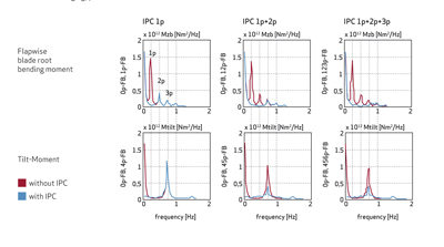
When designing strategies to counterbalance the forces discussed above, a first step is an analysis: The Fourier analysis gives what is usually called the 1p, 2p, 3p, components of the loads. Classic IPC, which is most often used, only compensates for the 1p component. Other components can also be addressed by IPC but their compensation requires increased pitch activity and more dynamic control systems. Highly dynamic control systems would also be necessary to fully benefit from recent developments in wind measurement. The newest measurement technologies such as LIDAR (Light Detection and Ranging) provide real-time information on wind conditions and forecasts for the next few seconds. Based on this information it becomes possible to prevent peak loads by using IPC to develop preventative load alleviation strategies. [4]

Advanced blade sensing systems provide information about the load condition of the rotor blades in real-time. These monitoring systems rely on sensor technology using e.g., optic fibers embedded in the rotor blade material. Using IPC and blade sensing systems to adjust pitch actions to the actual loads measured for each rotor blade individually becomes an obvious choice. Figure 6

Economic Considerations and Technical Challenges
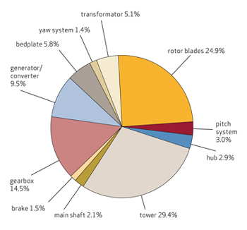
Compared to collective pitch systems, IPC systems require higher investment costs. These investments relate particularly to a more complex control strategy, higher requirements for the pitch motor and increased fatigue loads on the pitch bearings and pitch gears.  However, as shown in the graphic below, the cost of any pitch system is low in comparison to the overall cost of a wind turbine. The savings in other components due to reduction of fatigue loads have the potential to compensate for the extra investment for an IPC system. When creating the business case, turbine designers would therefore need to consider the entire cost of a wind turbine. When not only investment costs, but also O&M costs are taken into account, IPC could be even more beneficial. This is due to load reductions, which translate into an increased lifetime of turbines. Experts predict increasing potential for reducing the total cost of ownership for turbines using IPC systems. To achieve this it would be necessary to optimize and adjust existing systems through careful evaluation of, not only the components of the IPC system, but of the entire turbine design. Focus should be on the evaluation of extreme loads during start-up and shut-down, fatigue loads on the main shaft and main bearing, the use of new types of pitch bearings and the optimized utilization of load sensors.

For these reasons, the best and fastest results are expected through close cooperation between manufacturers of turbines and IPC systems.

Expertise and Partnership Approach
In the field of pitch control systems for wind turbines, Moog has in-depth experience highlighted by an installed base of more than 25,000 systems. We are a supplier of all necessary products for pitch control systems, including software and hardware. This means that critical products such as Pitch Servo Drive, Pitch Motor, Slip Ring and Blade Sensing System are all designed and manufactured by Moog. A partnership approach in adapting to our clients’ needs is especially important. This approach is characterized by the flexibility to adjust to the technology chosen. We can tailor our products for example to the needs of electric as well as hydraulic pitch systems. Figure 7

Demand For Renewable Resources
Demand for electrical power generated by renewable sources is increasing on a global scale. The prospects in the wind energy sector are especially promising. However, this development also brings new challenges including: Larger turbines, wind parks in remote areas with difficult climatic conditions and higher expectations on reliability, flexibility and predictability of electrical power generation. When turbines are getting larger, load reduction, especially for asymmetric loads caused by inhomogeneous wind fields, becomes more and more important. Consequently, the manufacturer anticipates that IPC will play an increasingly important role as the most common technology capable of compensating asymmetric loads. The ultimate aim of this cooperation is to reduce the overall cost of electrical power generated by wind turbines. To achieve this it is necessary to reduce the total cost related to the design, construction and operation of wind turbines to develop the wind energy solutions for the future.

Moog has supplied more than 27,000 systems and products to many of the world’s top-ten wind turbine manufacturers. The company’s wind industry products and expertise span both electric and hydraulic technologies. For example, by precisely monitoring wind loads on blades, the rotor monitoring system improves the turbine’s life span and maintenance costs. Predictive maintenance is vital to wind park operators because the cost of a shutdown and subsequent turbine repairs is high.

The Pitch Systems also improve safety when the wind turbine loses electrical power. The pitch system puts the turbine blades off-wind into a safe operating mode that protects the wind turbine from damage. When the wind blows at 25 meters per second (50 mph) or higher, a wind turbine needs a failsafe to put its blades at an angle where the load is reduced and the wind turbine stops. Found in the hub of the wind turbine, the Moog Pitch System consists of: control boxes containing Moog Pitch Servo Drives; Wind Pitch Servo Motors; and, a control system including software for remote diagnostics and back-up power. Figure 8


The company also offers slip ring solutions, which are critical to operation. Found inside the wind turbine’s nacelle, slip rings provide electrical signals and energy for blade pitch power and control. The fiber brush slip rings offer wind turbine owners a minimum of 100 million revolutions of operational life with no maintenance.   

Wednesday, February 20, 2013

NUMBER OF BLADES


Small-scale, multi-bladed turbines are still in use for water pumping.They are of relatively low aerodynamic efficiency but, with the large blade area, can provide a high starting torque (turning force). This enables the rotor to turn in very light winds and suits a water pumping duty.  

Most modern wind turbines have three blades, although in the 1980s and early 1990s some attempt was made to market one and two-bladed wind turbine designs.  
The single-bladed design (Figure 1) is the most structurally efficient for the rotor blade, as it has the greatest blade section dimensions with all the installed blade surface area in a single beam. It is normal to shut down (park) wind turbines in very high winds, in order to protect them from damage.  This is because they would generally experience much higher blade and tower loads if they continued to operate.  The one-bladed design allows unique parking strategies – with the single blade acting as wind vane upwind or downwind behind the tower – which may minimise storm loading impact.  However, there are a number of disadvantages.  With a counterweight to balance the rotor statically, there is reduced aerodynamic efficiency and complex dynamics requiring a blade hinge to relieve loads.  The designs of Riva Calzoni, MAN, Messerschmidt and others were of too high a tip speed to be acceptable in the modern European market from an acoustic point of view. However, just when it seemed that the era of single bladed turbines had ended, the Spanish company, ADES, has announced the development of a single bladed, pendular wind turbine in which the cyclic torque variations of the single bladed turbine are compensated by allowing the generator to swing like a pendulum on the gearbox output.  Moreover a new small scale single bladed design, the Thinair 102, rated 2 kW, is being marketed for home applications by the New Zealand company, Powerhouse Wind. 
Figure 1: Single-Bladed Wind Turbine
The two-bladed rotor design (Figure 2) is technically on a par with the established three-bladed design.  In order to obtain a potentially simpler and more efficient rotor structure with more options for rotor and nacelle erection, it is necessary either to accept higher cyclic loading or to introduce a teeter hinge, which is often complex.  The teeter hinge allows the two blades of the rotor to move as a single beam through typically ±7° in an out-of-plane rotation.  Allowing this small motion can much relieve loads in the wind turbine system, although some critical loads return when the teeter motion reaches its end limits.  The two-bladed rotor is a little less efficient aerodynamically than a three-bladed rotor.  
In general, there are small benefits of rotors having increasing number of blades.  This relates to minimising losses that take place at the blade tips.  These losses are, in aggregate, less for a large number of narrow blade tips than for a few wide ones.  
In rotor design, an operating speed or operating speed range is normally selected first, taking into account issues such as acoustic noise emission.  With the speed chosen, it then follows that there is an optimum total blade area for maximum rotor efficiency.  The number of blades is, in principle, open but more blades imply more slender blades for the fixed (optimum) total blade area.  This summarises the broad principles affecting blade numbers.
Note also that it is a complete misconception to think that doubling the number of blades would double the power of a rotor.  Rather, it would reduce power if the rotor was well designed in the first instance.

Figure 2: Two-Bladed Wind Turbine
 

It is hard to compare the two- and three-bladed designs on the basis of cost-benefit analysis.  It is generally incorrect to suppose that, in two-bladed rotor design, the cost of one of three blades has been saved, as two blades of a two-bladed rotor do not equate with two blades of a three-bladed rotor.  Two-bladed rotors generally run at much higher tip speed than three-bladed rotors, so most historical designs would have noise problems.  There is, however, no fundamental reason for the higher tip speed and this should be discounted in an objective technical comparison of the design merits of two versus three blades. 
The one-bladed rotor is perhaps more problematic technically, whilst the two-bladed rotor is basically acceptable technically.  The decisive factor in eliminating the one-blade rotor design from the commercial market, and in almost eliminating two-bladed design, has been visual impact.  The apparently unsteady passage of the blade or blades through a cycle of rotation has often been found to be objectionable.