How can we develop wind turbines that reduce the overall cost of electrical power generation? When answering this question, investment costs as well as operating and maintenance.
(O&M) costs have to be taken into consideration. One of the focal areas of this paper is load reduction as it can play a key role in increasing turbine efficiency and lifetime. When trying to reduce loads on turbine structures, designers focus on pitch control systems. We present recent technological developments and research results in this field, especially concerning Individual Pitch Control (IPC).
Given the opportunities and challenges in wind energy, we see the need for close cooperation between turbine designers and key system suppliers. This means companies combining their strengths and expertise by jointly engaging in research, as well as the development of prototypes and systems. Our partnership approach for developing future wind energy solutions is further explained at the end of this White Paper. Figure 1
Developments in the Wind Energy Sector
How are we going to meet our energy demands in the future? When governments and businesses worldwide draft strategies to answer this question, renewable energies play an increasingly important role. Among renewable energies, wind energy has gotten a head start in the race towards competitiveness. Electrical energy generated by wind power can already compete with energy generated by fossil or nuclear sources. [1]
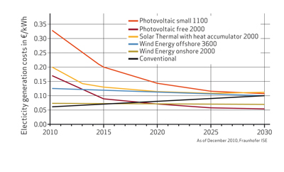
According to a study of the Fraunhofer ISE from December 2010, wind energy plants in locations with favorable wind conditions can already compete with conventional power plants. The costs for electricity generated by onshore wind parks are currently 0.06 to 0.08 €/kWh, which is in the range of electricity generation costs of conventional power plants using coal, lignite or nuclear fuels. [1] Consequently, wind parks are emerging from the state of research or pilot projects to commercially attractive investments. Large energy companies are increasingly investing in wind power. Among these investors are companies specialized in wind power but also electrical power suppliers who are relying on a mix of fossil, nuclear and renewable energy sources. When planning new wind parks, especially in Europe, one of the main hurdles is getting approval from authorities. Due to regulations with respect to landscape protection and noise control, the sites available for new wind parks are increasingly located offshore or, in the case of onshore installations, in remote areas. These sites are often characterized by poor access, extreme climatic conditions or non-ideal wind conditions. For the manufacturers of wind turbines this means facing new challenges: their wind turbines need to withstand extreme temperatures and work efficiently for a wider range of wind speeds. The installation of turbines in areas with poor access also places increased emphasis on operating and maintenance (O&M) costs. Figure 2
The growing importance of wind energy as a source for electrical power generation leads to stricter requirements concerning reliability and predictability of the power supply. Meeting grid code requirements with respect to frequency and voltage becomes more and more important for operators of wind parks. Large energy companies engaged in the wind power business are likely to focus their development efforts on meeting these requirements. [2]
The necessity to lower the overall cost of electrical power generated by wind turbines (cost per mega watt) has led to a trend towards larger turbine sizes. Especially for offshore installations the cost of the foundation represents a substantial part of the overall investment cost. It proved to be more cost efficient to build wind parks with fewer large size turbines than a large number of smaller turbines. [3]
Evolution of Standard Rotor Diameters
However, larger turbines with longer rotor blades and higher tower structures are creating technical challenges for turbine designers. The longer the rotor blades, the stronger the effect of any in homogeneities of the incoming wind field. Examples of such in homogeneities are lower wind speeds close to the ground and higher speeds with increasing distance from the ground (wind shear). Such a gradient of the wind speed translates into an asymmetric load on the rotor blades. The feasibility and technical challenges of large wind turbines has been the subject of recent studies and publications, notably the upwind project sponsored by the European Commission. While the power output of commercial wind turbines is usually in the range of 1 to 7 MW, the upwind project evaluates the feasibility of a 20 MW turbine. [4] [5]

Individual Pitch Control
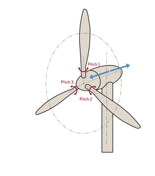
How can designers build wind turbines with longer lifetimes? Recent economic and technical developments such as the pressure to reduce the overall cost of electricity generated by wind turbines, the necessity to reduce O&M costs as well as increased emphasis on reliability and predictability of power production make it urgent to find a technical solution to that question. Load reduction is a key element of the solution. In addition, load reduction gains an increasing importance due to the trend towards larger wind turbines. Individual pitch control (IPC) plays a key role in compensating loads. So what is IPC? Any pitch control system allows control of the turbine speed and consequently the power output. It also acts as a brake, stopping the rotor by turning the blades. Moreover, pitch control, especially an IPC system, has a role in reducing fatigue loads on the turbine structures. Recently developed wind turbines are variable speed turbines capable of adapting to various wind conditions. This adaption is realized via new generator concepts on the one hand, and a pitch control system on the other hand. Pitch control means the turning of rotor blades between 0° and 90°. When wind speeds are below rated power, typically below 12 m/s, the rotor blades are turned fully towards the wind which means that the pitch is positioned at 0°. Figure 4

At increasing wind speeds the pitch of the blades is controlled in order to limit the power output of the turbine to its nominal value. When wind speeds reach a predefined threshold, typically 28 m/s, the turbine stops power production by turning the blades to a 90° position.
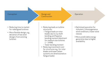
Collective pitch control adjusts the pitch of all rotor blades to the same angle at the same time. In contrast, IPC dynamically and individually adjusts the pitch of each rotor blade. Based on current individual loads this pitch adjustment is carried out in real-time. The main benefit of IPC is the reduction of fatigue loads on the rotor blades, the hub, and mainframe and tower structures. In order to compensate these loads, especially symmetric loads caused by inhomogeneous wind fields, the pitch of each rotor blade has to be adjusted independently from the other blades. A reduction of fatigue loads has two considerable advantages: It allows lighter designs and translates into longer lifetimes of wind turbines. What is meant by lighter designs? In cases where components are designed according to fatigue loads, a reduction of these loads allows savings in cost and material notably for the rotor blades and the tower structure, which are the most expensive elements of a wind turbine. Moreover, lighter rotor blades enable a more efficient turbine, especially in low wind conditions. Finally the load reduction through IPC gives designers the option to develop low wind turbines from existing designs, which means a reduction of time to market.
Load Reduction – A Technical Overview
During start-up, regular operation (power generation) and shutdown a wind turbine is subject to various forces causing peak loads and fatigue loads. In the context of this paper we shall focus on fatigue loads because they can be influenced by pitch control systems most effectively. Let us consider a wind turbine in operation at nominal wind speed and above, and have a look at the forces acting on the main elements of the turbine e.g., rotor blades, hub, mainframe, and tower. The rotor blades are subject to periodic bending forces. These bending forces are acting in two ways: First, edgewise bending in the direction of the rotor movement and second flap wise bending in the direction perpendicular to the plane of movement. There are also forces on the hub, mainframe and tower structures. These forces have two effects, in particular on the tower: The yaw moment (Myaw) is twisting and the tilt moment (Mtilt) is bending it. Figure 5
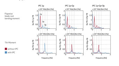
When designing strategies to counterbalance the forces discussed above, a first step is an analysis: The Fourier analysis gives what is usually called the 1p, 2p, 3p, components of the loads. Classic IPC, which is most often used, only compensates for the 1p component. Other components can also be addressed by IPC but their compensation requires increased pitch activity and more dynamic control systems. Highly dynamic control systems would also be necessary to fully benefit from recent developments in wind measurement. The newest measurement technologies such as LIDAR (Light Detection and Ranging) provide real-time information on wind conditions and forecasts for the next few seconds. Based on this information it becomes possible to prevent peak loads by using IPC to develop preventative load alleviation strategies. [4]
Advanced blade sensing systems provide information about the load condition of the rotor blades in real-time. These monitoring systems rely on sensor technology using e.g., optic fibers embedded in the rotor blade material. Using IPC and blade sensing systems to adjust pitch actions to the actual loads measured for each rotor blade individually becomes an obvious choice. Figure 6
Economic Considerations and Technical Challenges
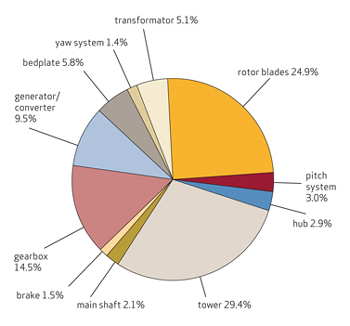
Compared to collective pitch systems, IPC systems require higher investment costs. These investments relate particularly to a more complex control strategy, higher requirements for the pitch motor and increased fatigue loads on the pitch bearings and pitch gears. However, as shown in the graphic below, the cost of any pitch system is low in comparison to the overall cost of a wind turbine. The savings in other components due to reduction of fatigue loads have the potential to compensate for the extra investment for an IPC system. When creating the business case, turbine designers would therefore need to consider the entire cost of a wind turbine. When not only investment costs, but also O&M costs are taken into account, IPC could be even more beneficial. This is due to load reductions, which translate into an increased lifetime of turbines. Experts predict increasing potential for reducing the total cost of ownership for turbines using IPC systems. To achieve this it would be necessary to optimize and adjust existing systems through careful evaluation of, not only the components of the IPC system, but of the entire turbine design. Focus should be on the evaluation of extreme loads during start-up and shut-down, fatigue loads on the main shaft and main bearing, the use of new types of pitch bearings and the optimized utilization of load sensors.
For these reasons, the best and fastest results are expected through close cooperation between manufacturers of turbines and IPC systems.
Expertise and Partnership Approach
In the field of pitch control systems for wind turbines, Moog has in-depth experience highlighted by an installed base of more than 25,000 systems. We are a supplier of all necessary products for pitch control systems, including software and hardware. This means that critical products such as Pitch Servo Drive, Pitch Motor, Slip Ring and Blade Sensing System are all designed and manufactured by Moog. A partnership approach in adapting to our clients’ needs is especially important. This approach is characterized by the flexibility to adjust to the technology chosen. We can tailor our products for example to the needs of electric as well as hydraulic pitch systems. Figure 7
Demand For Renewable Resources
Demand for electrical power generated by renewable sources is increasing on a global scale. The prospects in the wind energy sector are especially promising. However, this development also brings new challenges including: Larger turbines, wind parks in remote areas with difficult climatic conditions and higher expectations on reliability, flexibility and predictability of electrical power generation. When turbines are getting larger, load reduction, especially for asymmetric loads caused by inhomogeneous wind fields, becomes more and more important. Consequently, the manufacturer anticipates that IPC will play an increasingly important role as the most common technology capable of compensating asymmetric loads. The ultimate aim of this cooperation is to reduce the overall cost of electrical power generated by wind turbines. To achieve this it is necessary to reduce the total cost related to the design, construction and operation of wind turbines to develop the wind energy solutions for the future.
Moog has supplied more than 27,000 systems and products to many of the world’s top-ten wind turbine manufacturers. The company’s wind industry products and expertise span both electric and hydraulic technologies. For example, by precisely monitoring wind loads on blades, the rotor monitoring system improves the turbine’s life span and maintenance costs. Predictive maintenance is vital to wind park operators because the cost of a shutdown and subsequent turbine repairs is high.
The Pitch Systems also improve safety when the wind turbine loses electrical power. The pitch system puts the turbine blades off-wind into a safe operating mode that protects the wind turbine from damage. When the wind blows at 25 meters per second (50 mph) or higher, a wind turbine needs a failsafe to put its blades at an angle where the load is reduced and the wind turbine stops. Found in the hub of the wind turbine, the Moog Pitch System consists of: control boxes containing Moog Pitch Servo Drives; Wind Pitch Servo Motors; and, a control system including software for remote diagnostics and back-up power. Figure 8

The company also offers slip ring solutions, which are critical to operation. Found inside the wind turbine’s nacelle, slip rings provide electrical signals and energy for blade pitch power and control. The fiber brush slip rings offer wind turbine owners a minimum of 100 million revolutions of operational life with no maintenance.
(O&M) costs have to be taken into consideration. One of the focal areas of this paper is load reduction as it can play a key role in increasing turbine efficiency and lifetime. When trying to reduce loads on turbine structures, designers focus on pitch control systems. We present recent technological developments and research results in this field, especially concerning Individual Pitch Control (IPC).
Given the opportunities and challenges in wind energy, we see the need for close cooperation between turbine designers and key system suppliers. This means companies combining their strengths and expertise by jointly engaging in research, as well as the development of prototypes and systems. Our partnership approach for developing future wind energy solutions is further explained at the end of this White Paper. Figure 1
Developments in the Wind Energy Sector
How are we going to meet our energy demands in the future? When governments and businesses worldwide draft strategies to answer this question, renewable energies play an increasingly important role. Among renewable energies, wind energy has gotten a head start in the race towards competitiveness. Electrical energy generated by wind power can already compete with energy generated by fossil or nuclear sources. [1]
According to a study of the Fraunhofer ISE from December 2010, wind energy plants in locations with favorable wind conditions can already compete with conventional power plants. The costs for electricity generated by onshore wind parks are currently 0.06 to 0.08 €/kWh, which is in the range of electricity generation costs of conventional power plants using coal, lignite or nuclear fuels. [1] Consequently, wind parks are emerging from the state of research or pilot projects to commercially attractive investments. Large energy companies are increasingly investing in wind power. Among these investors are companies specialized in wind power but also electrical power suppliers who are relying on a mix of fossil, nuclear and renewable energy sources. When planning new wind parks, especially in Europe, one of the main hurdles is getting approval from authorities. Due to regulations with respect to landscape protection and noise control, the sites available for new wind parks are increasingly located offshore or, in the case of onshore installations, in remote areas. These sites are often characterized by poor access, extreme climatic conditions or non-ideal wind conditions. For the manufacturers of wind turbines this means facing new challenges: their wind turbines need to withstand extreme temperatures and work efficiently for a wider range of wind speeds. The installation of turbines in areas with poor access also places increased emphasis on operating and maintenance (O&M) costs. Figure 2
The growing importance of wind energy as a source for electrical power generation leads to stricter requirements concerning reliability and predictability of the power supply. Meeting grid code requirements with respect to frequency and voltage becomes more and more important for operators of wind parks. Large energy companies engaged in the wind power business are likely to focus their development efforts on meeting these requirements. [2]
The necessity to lower the overall cost of electrical power generated by wind turbines (cost per mega watt) has led to a trend towards larger turbine sizes. Especially for offshore installations the cost of the foundation represents a substantial part of the overall investment cost. It proved to be more cost efficient to build wind parks with fewer large size turbines than a large number of smaller turbines. [3]
Evolution of Standard Rotor Diameters
However, larger turbines with longer rotor blades and higher tower structures are creating technical challenges for turbine designers. The longer the rotor blades, the stronger the effect of any in homogeneities of the incoming wind field. Examples of such in homogeneities are lower wind speeds close to the ground and higher speeds with increasing distance from the ground (wind shear). Such a gradient of the wind speed translates into an asymmetric load on the rotor blades. The feasibility and technical challenges of large wind turbines has been the subject of recent studies and publications, notably the upwind project sponsored by the European Commission. While the power output of commercial wind turbines is usually in the range of 1 to 7 MW, the upwind project evaluates the feasibility of a 20 MW turbine. [4] [5]
Individual Pitch Control
How can designers build wind turbines with longer lifetimes? Recent economic and technical developments such as the pressure to reduce the overall cost of electricity generated by wind turbines, the necessity to reduce O&M costs as well as increased emphasis on reliability and predictability of power production make it urgent to find a technical solution to that question. Load reduction is a key element of the solution. In addition, load reduction gains an increasing importance due to the trend towards larger wind turbines. Individual pitch control (IPC) plays a key role in compensating loads. So what is IPC? Any pitch control system allows control of the turbine speed and consequently the power output. It also acts as a brake, stopping the rotor by turning the blades. Moreover, pitch control, especially an IPC system, has a role in reducing fatigue loads on the turbine structures. Recently developed wind turbines are variable speed turbines capable of adapting to various wind conditions. This adaption is realized via new generator concepts on the one hand, and a pitch control system on the other hand. Pitch control means the turning of rotor blades between 0° and 90°. When wind speeds are below rated power, typically below 12 m/s, the rotor blades are turned fully towards the wind which means that the pitch is positioned at 0°. Figure 4
At increasing wind speeds the pitch of the blades is controlled in order to limit the power output of the turbine to its nominal value. When wind speeds reach a predefined threshold, typically 28 m/s, the turbine stops power production by turning the blades to a 90° position.
Collective pitch control adjusts the pitch of all rotor blades to the same angle at the same time. In contrast, IPC dynamically and individually adjusts the pitch of each rotor blade. Based on current individual loads this pitch adjustment is carried out in real-time. The main benefit of IPC is the reduction of fatigue loads on the rotor blades, the hub, and mainframe and tower structures. In order to compensate these loads, especially symmetric loads caused by inhomogeneous wind fields, the pitch of each rotor blade has to be adjusted independently from the other blades. A reduction of fatigue loads has two considerable advantages: It allows lighter designs and translates into longer lifetimes of wind turbines. What is meant by lighter designs? In cases where components are designed according to fatigue loads, a reduction of these loads allows savings in cost and material notably for the rotor blades and the tower structure, which are the most expensive elements of a wind turbine. Moreover, lighter rotor blades enable a more efficient turbine, especially in low wind conditions. Finally the load reduction through IPC gives designers the option to develop low wind turbines from existing designs, which means a reduction of time to market.
Load Reduction – A Technical Overview
During start-up, regular operation (power generation) and shutdown a wind turbine is subject to various forces causing peak loads and fatigue loads. In the context of this paper we shall focus on fatigue loads because they can be influenced by pitch control systems most effectively. Let us consider a wind turbine in operation at nominal wind speed and above, and have a look at the forces acting on the main elements of the turbine e.g., rotor blades, hub, mainframe, and tower. The rotor blades are subject to periodic bending forces. These bending forces are acting in two ways: First, edgewise bending in the direction of the rotor movement and second flap wise bending in the direction perpendicular to the plane of movement. There are also forces on the hub, mainframe and tower structures. These forces have two effects, in particular on the tower: The yaw moment (Myaw) is twisting and the tilt moment (Mtilt) is bending it. Figure 5
When designing strategies to counterbalance the forces discussed above, a first step is an analysis: The Fourier analysis gives what is usually called the 1p, 2p, 3p, components of the loads. Classic IPC, which is most often used, only compensates for the 1p component. Other components can also be addressed by IPC but their compensation requires increased pitch activity and more dynamic control systems. Highly dynamic control systems would also be necessary to fully benefit from recent developments in wind measurement. The newest measurement technologies such as LIDAR (Light Detection and Ranging) provide real-time information on wind conditions and forecasts for the next few seconds. Based on this information it becomes possible to prevent peak loads by using IPC to develop preventative load alleviation strategies. [4]
Advanced blade sensing systems provide information about the load condition of the rotor blades in real-time. These monitoring systems rely on sensor technology using e.g., optic fibers embedded in the rotor blade material. Using IPC and blade sensing systems to adjust pitch actions to the actual loads measured for each rotor blade individually becomes an obvious choice. Figure 6
Economic Considerations and Technical Challenges
Compared to collective pitch systems, IPC systems require higher investment costs. These investments relate particularly to a more complex control strategy, higher requirements for the pitch motor and increased fatigue loads on the pitch bearings and pitch gears. However, as shown in the graphic below, the cost of any pitch system is low in comparison to the overall cost of a wind turbine. The savings in other components due to reduction of fatigue loads have the potential to compensate for the extra investment for an IPC system. When creating the business case, turbine designers would therefore need to consider the entire cost of a wind turbine. When not only investment costs, but also O&M costs are taken into account, IPC could be even more beneficial. This is due to load reductions, which translate into an increased lifetime of turbines. Experts predict increasing potential for reducing the total cost of ownership for turbines using IPC systems. To achieve this it would be necessary to optimize and adjust existing systems through careful evaluation of, not only the components of the IPC system, but of the entire turbine design. Focus should be on the evaluation of extreme loads during start-up and shut-down, fatigue loads on the main shaft and main bearing, the use of new types of pitch bearings and the optimized utilization of load sensors.
For these reasons, the best and fastest results are expected through close cooperation between manufacturers of turbines and IPC systems.
Expertise and Partnership Approach
In the field of pitch control systems for wind turbines, Moog has in-depth experience highlighted by an installed base of more than 25,000 systems. We are a supplier of all necessary products for pitch control systems, including software and hardware. This means that critical products such as Pitch Servo Drive, Pitch Motor, Slip Ring and Blade Sensing System are all designed and manufactured by Moog. A partnership approach in adapting to our clients’ needs is especially important. This approach is characterized by the flexibility to adjust to the technology chosen. We can tailor our products for example to the needs of electric as well as hydraulic pitch systems. Figure 7
Demand For Renewable Resources
Demand for electrical power generated by renewable sources is increasing on a global scale. The prospects in the wind energy sector are especially promising. However, this development also brings new challenges including: Larger turbines, wind parks in remote areas with difficult climatic conditions and higher expectations on reliability, flexibility and predictability of electrical power generation. When turbines are getting larger, load reduction, especially for asymmetric loads caused by inhomogeneous wind fields, becomes more and more important. Consequently, the manufacturer anticipates that IPC will play an increasingly important role as the most common technology capable of compensating asymmetric loads. The ultimate aim of this cooperation is to reduce the overall cost of electrical power generated by wind turbines. To achieve this it is necessary to reduce the total cost related to the design, construction and operation of wind turbines to develop the wind energy solutions for the future.
Moog has supplied more than 27,000 systems and products to many of the world’s top-ten wind turbine manufacturers. The company’s wind industry products and expertise span both electric and hydraulic technologies. For example, by precisely monitoring wind loads on blades, the rotor monitoring system improves the turbine’s life span and maintenance costs. Predictive maintenance is vital to wind park operators because the cost of a shutdown and subsequent turbine repairs is high.
The Pitch Systems also improve safety when the wind turbine loses electrical power. The pitch system puts the turbine blades off-wind into a safe operating mode that protects the wind turbine from damage. When the wind blows at 25 meters per second (50 mph) or higher, a wind turbine needs a failsafe to put its blades at an angle where the load is reduced and the wind turbine stops. Found in the hub of the wind turbine, the Moog Pitch System consists of: control boxes containing Moog Pitch Servo Drives; Wind Pitch Servo Motors; and, a control system including software for remote diagnostics and back-up power. Figure 8
The company also offers slip ring solutions, which are critical to operation. Found inside the wind turbine’s nacelle, slip rings provide electrical signals and energy for blade pitch power and control. The fiber brush slip rings offer wind turbine owners a minimum of 100 million revolutions of operational life with no maintenance.


 Posts
Posts